Select "balances at joints" and select joint . Members of a truss can be subjected to axial compression or axial tension. WebPart 1. 0
Reading, MA: [more] Contributed by: Rachael L. Baumann (September 2017) Additional contributions by: John L. Falconer The user has to give the co-ordinated of the nodes, the connections of the trusses, forces, and un-constrained displacements as input. The method of joints is a process used to solve for the unknown forces acting on members of a truss. Warren Truss Analysis. Truss Tutorial 1: Analysis and Calculation using Method of Joints Step 1: Calculate the Reactions at the Supports. F_{A D}=12-24.17 \cos 36.87^{\circ}=-7.34 \mathrm{kN} After choosing your joint, you will draw another free-body diagram. hb```Ol"B cg`a%s Internally determinate trusses are those whose members are so arranged that just enough triangular cells are formed to prevent geometrical instability of the system. jointObj = rigidBodyJoint(jname,jtype) Truss Example-Method of Joints (Edited) [Video]. The detailed procedure for analysis by this method is presented below. With these equations, you can calculate the side length of a triangle if the angle theta is known. You can also take it one step further to explore and optimize your design using design of experiment and optimization techniques for desired performance. A joint is any point at which a member is connected to another, typically by welding, pins or rivets. A truss is one of the major types of engineering structures and is especially used in the design of bridges and buildings. Remove an entire body and get the resulting subtree using removeBody. +\uparrow \sum F_{y}=0 \\ offers. if the force causes the body to rotate clockwise, it is considered negative. Find the force acting in each of the members of the truss shown below. WebHow to calculate Joint Probability Distribution in MATLAB? (default). 2. To perform any simulation workflows, generate the simulink model of the mechanism by using the makeBlockDiagram method. +\curvearrowleft \sum M_{C}=0 \\ Specify the body name that you are attaching the rigid body to. 5.6.2 Analysis of Trusses by Method of Joint. Other MathWorks country sites are not optimized for visits from your location. WebHow to calculate Joint Probability Distribution in MATLAB? Note that the direction of the arrows are drawn in "focus on joint" because we know the correct direction. A 90 degree angle is typically denoted in diagrams as a square in the corner of the triangle. In the diagram of the simple truss, the forces are represented by black arrows in units of Newtons. Use setFixedTransform to specify the body-to-body transformation using DH parameters. Fixed transform from joint to parent frame, Fixed transform from child body to joint frame.
The Multibody object provides a method jointPrimitivePaths to list the paths to all the joint primitives in the mechanism. Joint name, returned as a string scalar or character vector. Thus, \(\begin{array}{l} Step 2: Consider one of the Supports:. Replace the joint on the L3 body. +\uparrow \sum F_{y}=0 \\ Based on your location, we recommend that you select: . The limits define the linear motion Trusses are designed to support loads, such as the weight of people, and are stationary. Create a revolute joint. Introduction to Robotics: Mechanics and Control. [2] Siciliano, Bruno. After creating the geometrical structure model by using geom1 and geom2 functions and entering the boundary conditions of the physical problem (bc), external applied loads (extloads) must be entered. The Method of Joints. A normal force for each two force member connected to that joint. (University of Colorado Boulder, Department of Chemical and Biological Engineering) Based on your location, we recommend that you select: . -you will use trigonometry to break the reactionary force at A into horizontal and vertical components. offers. The method of joint involves successively isolating each joint in a truss system and determining the axial forces in the members meeting at the joint by applying the equations of equilibrium. In this tutorial, we will explain how to use the method of joints to calculate the internal member forces in a truss system or structure. It is important to remember that all the forces must sum to zero for both the x and y-direction. If this initial assumption is incorrect, the computed values of the axial forces will be negative, signifying compression.
Based on your location, we recommend that you select: . The LibreTexts libraries arePowered by NICE CXone Expertand are supported by the Department of Education Open Textbook Pilot Project, the UC Davis Office of the Provost, the UC Davis Library, the California State University Affordable Learning Solutions Program, and Merlot. If you assumed that all forces were tensile earlier, remember that negative answers indicate compressive forces in the members. Besides, only axial loads are assumed, so that torsion, bending and shear stresses are neglected and cannot be determined by this method. Other MathWorks country Procedure for Analysis. Method of section: This method entails passing an imaginary section through the truss to divide it into two sections. Your guide to SkyCiv software - tutorials, how-to guides and technical articles. \end{array}\). Use this list as one of the inputs to the custom function randomOpPoint that creates an operating point specifying random velocities for all the joints. +\rightarrow \sum F_{x}=0 \\ slides along a given axis. Remember to specify if each member is in tension or compression. Now that the forces on the joint have been broken into horizontal and vertical components the two summation equations can be written as shown. WebThis means that to solve completely for the forces acting on a joint, we must select a joint with no more than two unknown forces involved. WebCreate a Mechanism with Different Joints in MATLAB This example shows how to model a mechanism that contains different types of joints in MATLAB. -80(6)+80(3)-F_{C D}(3)=0 \\
Specify the previous body name when calling addBody to attach it. We can assume any unknown member to be either tension or compression. m+r<2 j \quad \text { structure is statically unstable } \\ \end{array}\). Any external reaction or load forces that may be acting at that joint. Recall that in this method, a free-body diagram of each joint is sketched and the forces acting on the joint are summed in the x- ** note: when drawing free-body diagrams of the joints with unknown force members, the direction( the force pointing away from the joint or towards the joint) in which you draw the force is arbitrary. Method of Joints The second equation will be written for the forces on the truss in the horizontal direction. After creating the geometrical structure model by using geom1 and geom2 functions and entering the boundary conditions of the physical problem (bc), external applied loads (extloads) must be entered. Based on the simple truss used in the last step, this joint would be either A or B. showdetails lists all the bodies in the MATLAB command window. The DH parameters are relative to the previous row in the matrix, corresponding to the previous joint attachment. To complete your truss analysis you will need: - Scientific calculator ( can calculate sine, cosine, and tangential angles). Method of Joints using MATLAB We have seen that the forces in each member of a truss can be found by the Method of Joints. on Step 1, Determine the forces in members AB,AF and GF and then in BC,BE and EF. Loads on Truss Nodes .
robotics.Joint. It also shows a way of setting operating point targets for the joint primitives of the joints. Recall that in this method, a free-body diagram of each joint is sketched and the forces acting on the joint are summed in the x- A factor of safety for bridges tells tell the public how many people, cars, etc. Help improved. MathWorks is the leading developer of mathematical computing software for engineers and scientists. The forces exerted at point A are the force of tension from the cord on the left, the force of tension from the cord on the right and the force of the weight of the crate due to gravity pulling down. Verify that your robot was built properly by using the showdetails or show function. { "5.00:_Video_Introduction_to_Chapter_5" : "property get [Map MindTouch.Deki.Logic.ExtensionProcessorQueryProvider+<>c__DisplayClass228_0.b__1]()", "5.01:_Structures" : "property get [Map MindTouch.Deki.Logic.ExtensionProcessorQueryProvider+<>c__DisplayClass228_0.b__1]()", "5.02:_Two-Force_Members" : "property get [Map MindTouch.Deki.Logic.ExtensionProcessorQueryProvider+<>c__DisplayClass228_0.b__1]()", "5.03:_Trusses" : "property get [Map MindTouch.Deki.Logic.ExtensionProcessorQueryProvider+<>c__DisplayClass228_0.b__1]()", "5.04:_Method_of_Joints" : "property get [Map MindTouch.Deki.Logic.ExtensionProcessorQueryProvider+<>c__DisplayClass228_0.b__1]()", "5.05:_Method_of_Sections" : "property get [Map MindTouch.Deki.Logic.ExtensionProcessorQueryProvider+<>c__DisplayClass228_0.b__1]()", "5.06:_Frames_and_Machines" : "property get [Map MindTouch.Deki.Logic.ExtensionProcessorQueryProvider+<>c__DisplayClass228_0.b__1]()", "5.07:_Analysis_of_Frames_and_Machines" : "property get [Map MindTouch.Deki.Logic.ExtensionProcessorQueryProvider+<>c__DisplayClass228_0.b__1]()", "5.08:_Chapter_5_Homework_Problems" : "property get [Map MindTouch.Deki.Logic.ExtensionProcessorQueryProvider+<>c__DisplayClass228_0.b__1]()" }, { "00:_Front_Matter" : "property get [Map MindTouch.Deki.Logic.ExtensionProcessorQueryProvider+<>c__DisplayClass228_0.b__1]()", "01:_Basics_of_Newtonian_Mechanics" : "property get [Map MindTouch.Deki.Logic.ExtensionProcessorQueryProvider+<>c__DisplayClass228_0.b__1]()", "02:_Static_Equilibrium_in_Concurrent_Force_Systems" : "property get [Map MindTouch.Deki.Logic.ExtensionProcessorQueryProvider+<>c__DisplayClass228_0.b__1]()", "03:_Static_Equilibrium_in_Rigid_Body_Systems" : "property get [Map MindTouch.Deki.Logic.ExtensionProcessorQueryProvider+<>c__DisplayClass228_0.b__1]()", "04:_Statically_Equivalent_Systems" : "property get [Map MindTouch.Deki.Logic.ExtensionProcessorQueryProvider+<>c__DisplayClass228_0.b__1]()", "05:_Engineering_Structures" : "property get [Map MindTouch.Deki.Logic.ExtensionProcessorQueryProvider+<>c__DisplayClass228_0.b__1]()", "06:_Friction_and_Friction_Applications" : "property get [Map MindTouch.Deki.Logic.ExtensionProcessorQueryProvider+<>c__DisplayClass228_0.b__1]()", "07:_Particle_Kinematics" : "property get [Map MindTouch.Deki.Logic.ExtensionProcessorQueryProvider+<>c__DisplayClass228_0.b__1]()", "08:_Newton\'s_Second_Law_for_Particles" : "property get [Map MindTouch.Deki.Logic.ExtensionProcessorQueryProvider+<>c__DisplayClass228_0.b__1]()", "09:_Work_and_Energy_in_Particles" : "property get [Map MindTouch.Deki.Logic.ExtensionProcessorQueryProvider+<>c__DisplayClass228_0.b__1]()", "10:_Impulse_and_Momentum_in_Particles" : "property get [Map MindTouch.Deki.Logic.ExtensionProcessorQueryProvider+<>c__DisplayClass228_0.b__1]()", "11:_Rigid_Body_Kinematics" : "property get [Map MindTouch.Deki.Logic.ExtensionProcessorQueryProvider+<>c__DisplayClass228_0.b__1]()", "12:_Newton\'s_Second_Law_for_Rigid_Bodies" : "property get [Map MindTouch.Deki.Logic.ExtensionProcessorQueryProvider+<>c__DisplayClass228_0.b__1]()", "13:_Work_and_Energy_in_Rigid_Bodies" : "property get [Map MindTouch.Deki.Logic.ExtensionProcessorQueryProvider+<>c__DisplayClass228_0.b__1]()", "14:_Impulse_and_Momentum_in_Rigid_Bodies" : "property get [Map MindTouch.Deki.Logic.ExtensionProcessorQueryProvider+<>c__DisplayClass228_0.b__1]()", "15:_Vibrations_with_One_Degree_of_Freedom" : "property get [Map MindTouch.Deki.Logic.ExtensionProcessorQueryProvider+<>c__DisplayClass228_0.b__1]()", "16:_Appendix_1_-_Vector_and_Matrix_Math" : "property get [Map MindTouch.Deki.Logic.ExtensionProcessorQueryProvider+<>c__DisplayClass228_0.b__1]()", "17:_Appendix_2_-_Moment_Integrals" : "property get [Map MindTouch.Deki.Logic.ExtensionProcessorQueryProvider+<>c__DisplayClass228_0.b__1]()", "zz:_Back_Matter" : "property get [Map MindTouch.Deki.Logic.ExtensionProcessorQueryProvider+<>c__DisplayClass228_0.b__1]()" }, [ "article:topic", "license:ccbysa", "showtoc:no", "authorname:jmoore", "method of joints", "space trusses", "licenseversion:40", "source@http://mechanicsmap.psu.edu" ], https://eng.libretexts.org/@app/auth/3/login?returnto=https%3A%2F%2Feng.libretexts.org%2FBookshelves%2FMechanical_Engineering%2FMechanics_Map_(Moore_et_al. WebAnnex 1: Truss Analysis. as pulling away from the joint). The user has to give the co-ordinated of the nodes, the connections of the trusses, forces, and un-constrained displacements as input. Joint B is only acted on by one purely horizontal force, represented by Fbd. WebTo add a rigid body: Create a rigidBody object and give it a unique name. Did you make this project? (default). Each rigid body is added one at a time, with the child-to-parent transform specified by the joint object. The analysis of the truss reduces to computing the forces in the various members, which are either in tension or compression. Web675K views 6 years ago Statics This engineering statics tutorial goes over a full example using the method of joints for truss analysis.
Also called a pin or hinge joint. Press, 1994, pp. Create a rigidBodyJoint object and give it a unique name. WebPart 1. - Addition of forces in the horizontal and vertical directions, The Instructable should take 30 minutes to an hour to work through, depending on your prior math knowledge. It, therefore, has no force in it and is known as a Zero Member. Add the rigid body to the tree. joint. The assumptions in the analysis of plane trusses include the following: 1.Members of trusses are connected at their ends by frictionless pins. Check "focus on joint" to zoom in on the members around the joint and display the force balances. Verify the stability and determinacy of the structure. F_{B C} \sin 53.13=-15+24.17 \sin 53.13= \\ Add a rigid body and corresponding joint to a rigid body tree. To determine the components separately we will use trigonometry of a right triangle.
creates a fixed joint with the specified name. In our example, this works out to be 2.5 kN in an upward direction. 24 May 2020. \[ \sum \vec{F} = 0 \] \[ \sum F_x = 0 \, ; \,\,\, \sum F_y = 0 \], In space trusses, the sum of the forces in the \(x\) direction will be zero, the sum of the forces in the \(y\) direction will be zero, and the sum of forces in the \(z\) direction will be zero for each of the joints.
To determine the axial forces in members meeting at joint \(A\), first isolate the joint from the truss and indicate the axial forces of members as \(F_{A B}\) and \(F_{A D}\), as shown in Figure 5.10c. Get a specific body to inspect the properties. It also shows a way of setting operating point targets for the joint primitives of the joints. type predefines certain properties when creating the joint. Since the Theory of Deformations is not considered in this program, displacements of the structures are not computed. You can now solve for the forces at joint B. First, we calculate the reactions at the supports. % Row 3: 3-DOF and 4-DOF multi-primitive joints, Create a Mechanism with Different Joints in MATLAB. All the members of the structure satisfy the simplification hypothesis of the method of joints. As an example of a free body diagram of an entire simple truss, consider this truss with joints A,B,C,D. A free-body diagram is a diagram that clearly indicates all forces acting on a body, in this case the body being the truss. We also acknowledge previous National Science Foundation support under grant numbers 1246120, 1525057, and 1413739. Procedure for Analysis. WebThe method of joints analyzes the force in each member of a truss by breaking the truss down and calculating the forces at each individual joint. WebPart 1. freedom (DOF) joint that rotates around a given axis. Loads on Truss Nodes . First, calculate the reaction forces by doing a moment balance around joint and force balances in the and directions: where and are the reaction forces at joint in the and directions, is the reaction force at joint , is the width of the members and is the point load force at joint . In this program, the basic elimination approach is used to reduce the global matrix and find the displacements at the nodes. SkyCiv Truss can calculate the method of joints automatically for you. an attachment point. Now we consider the forces in the x-direction. This example shows how to model a mechanism that contains different types of joints in MATLAB. Again, if we look at summing the forces in the x-direction, we can see there is only one member that has any force in the x-direction. Create a Multibody object and add the necessary components, such as WorldFrame and Gravity. Recall that in this method, a free-body diagram of each joint is sketched and the forces acting on the joint are summed in the x- $\Sigma F_x = 0$ and $\Sigma F_y = 0$, MATHalino - Engineering Mathematics Copyright 2023, Problem 404 Roof Truss - Method of Joints, Problem 406 Cantilever Truss - Method of Joints, Problem 407 Cantilever Truss - Method of Joints, Problem 408 Warren Truss - Method of Joints, Problem 409 Howe Roof Truss - Method of Joints, Problem 410 Pratt Roof Truss - Method of Joints, Problem 411 Cantilever Truss by Method of Joints, Problem 412 Right Triangular Truss by Method of Joints, Method of Joints | Analysis of Simple Trusses, Method of Sections | Analysis of Simple Trusses, Method of Members | Frames Containing Three-Force Members. 5.1 Classify the trusses shown in Figure P5.1a through Figure P5.1r. The last element of the DH parameters, theta, is ignored because the angle is dependent on the joint position. revolute 0 The method centers on the joints or connection points between the members, and it is usually the fastest and easiest way to solve for all the unknown forces in a truss structure. MathWorks is the leading developer of mathematical computing software for engineers and scientists. You have now learned how to analyze a simple truss by the method of joints. Bodies remain fixed To determine the number of unknown reactions in excess of the equation of equilibrium for the indeterminate trusses, additional equations must be formulated based on the compatibility of parts of the system. This will help you keep everything organized and consistent in later analysis. Accordingly, we know member 2 must be generating a force that is pulling the point to the right to maintain the forces in the x-direction. F_{D C}=F_{D A}=-7.34 \mathrm{kN} Procedure for Analysis. We also acknowledge previous National Science Foundation support under grant numbers 1246120, 1525057, and 1413739. Truss Tutorial 1: Analysis and Calculation using Method of Joints Step 1: Calculate the Reactions at the Supports. If this initial assumption is wrong, the calculated member forces will be negative, showing that they are in compression. You must create a new Joint object and use replaceJoint to ensure the downstream body geometry is unaffected. All assumptions of Rational Mechanics are made in order to mantain the structure as a rigid body. Your calculations will give you a negative or a positive number designating the real direction of the force. The order of the calculations shown is the order that the joints are solved in. You can also calculate the side length of a triangle if two of the side are known by using Pythagorea's Theorem which says the square of the hypotenuse is equal to the sum of the square of the adjacent side plus the square of the opposite (a^2+b^2=c^2). This page titled 5.6: Methods of Truss Analysis is shared under a CC BY-NC-SA 4.0 license and was authored, remixed, and/or curated by Ren Alderliesten (TU Delft Open) via source content that was edited to the style and standards of the LibreTexts platform; a detailed edit history is available upon request. If the rigid body that contains this joint is added to a robot model, the joint type predefines certain properties when creating the joint. If this initial assumption is wrong, the determined member axial force will be negative in the analysis, meaning that the member is in compression and not in tension. equilateral. PositionLimits. type. In our example, the horizontal distance is 3m while the vertical is 5m leaving us with the hypotenuse equal to approximately 5.83 m. Using this, we can deduce that the normal force component of member 1 is equal to (5.83)/(5) times the vertical force of 2.5 kN. A close examination will show that the joint that meets this requirement is joint \(G\). WebCreate a Mechanism with Different Joints in MATLAB This example shows how to model a mechanism that contains different types of joints in MATLAB. (default). This page titled 5.4: Method of Joints is shared under a CC BY-SA 4.0 license and was authored, remixed, and/or curated by Jacob Moore & Contributors (Mechanics Map) via source content that was edited to the style and standards of the LibreTexts platform; a detailed edit history is available upon request. In this program, the basic elimination approach is used to reduce the global matrix and find the displacements at the nodes. Using the method of joint, determine the axial force in each member of the truss shown in Figure 5.10a. In this situation, any force pushing up will have no possible resisting action, as there is no other member that is able to provide a downward force to keep the point static.
We can assume any unknown member to be either tension or compression. relative motion between two bodies. Now that we have the reaction forces we can start the analysis of the rest of this truss structure. A plot of the structure (numerating all nodes and elements) can be shown by using plotits2d function. Sine, Cosine and Tangent are the three main functions in trigonometry and are shortened to sin, cos and tan (as they are displayed on your calculator). Use the Denavit-Hartenberg (DH) parameters of the Puma560 robot to build a robot. MathWorks is the leading developer of mathematical computing software for engineers and scientists. London: Springer, DIY Arduino Camera Robot (Motorized Pan Tilt Head), Laser-Cut Infinity Dodecahedron (Fusion 360). name must be unique to access it off the rigid body tree. The Puma robot is a serial chain manipulator. Using the method of section, determine the axial forces in members \(CD\), \(CG\), and \(HG\) of the truss shown in Figure 5.12a. You can plug in the known side lengths and solve for the unknown. Select "reaction forces" to see how the reaction forces and are calculated. Apply the two equations \(\Sigma F_{X}=0\) and \(\Sigma F_{Y}=0\) to determine the member axial forces. An incorrect guess now though will simply lead to a negative solution later on. Method of Joints using MATLAB We have seen that the forces in each member of a truss can be found by the Method of Joints. "Method of Joints to Solve a Truss Problem", http://demonstrations.wolfram.com/MethodOfJointsToSolveATrussProblem/, Solving Mass Balances on a Distillation Column, Construct a McCabe-Thiele Diagram for Distillation, Construct an x-y Diagram for a Stripping Column, Construct an x-y Diagram for an Absorption Column, Construct a Conversion-Temperature Diagram for a Reversible Adiabatic Reaction, Reactor Rate and Conversion versus Space Velocity, Construct a T-x-y Diagram for Vapor-Liquid Equilibrium (VLE), Electrical Conductivity of Silicon Semiconductors, Vapor-Liquid Equilibrium Diagram for Non-Ideal Mixture, P-x-y and T-x-y Diagrams for Vapor-Liquid Equilibrium (VLE), Immiscible Liquids on Pressure-Composition Diagram, Apply the Hunter-Nash Method to Liquid-Liquid Extraction, Construct Single-Stage, Liquid-Liquid Extraction. It's funny that they still teach this to first years. joint. In the beginning, it is usually useful to label the members and the joints in your truss. Thus, taking the moment about \(G\) suggests the following: \(\begin{array}{l} After completing the analysis of joint \(A\), joint \(B\) or \(D\) can be analyzed, as there are only two unknown forces. The removed body is included in the subtree. Trusses can be externally or internally determinate or indeterminate. The Golden Gate Bridge has a unique truss incorporated into its design. The analysis for isosceles triangles will be similar. To calculate forces on a truss you will need to use trigonometry of a right triangle. Then, under the drop-down menu, select "calculate moment" to see the moment balance around joint and calculate the reaction force at joint . Published:September82017. MATLAB program for 2D truss analysis (FEM). This method involves passing an imaginary section through the truss so that it divides the system into two parts and cuts through members whose axial forces are desired. By default, the rigidBody object comes with a fixed joint.
Using this process and trigonometry, you may also be able to construct your own small scale truss. generate the predefined home configuration for an entire rigid body These forces are known as Axial Forces and are very important in truss analysis. Examples of physical and virtual connections between bodies 0.5] (default). The imaginary cut divides the truss into two parts. The point at which the moments are summed is arbitrary, but the best choice is a point that has multiple forces acting directly on it. WebThis means that to solve completely for the forces acting on a joint, we must select a joint with no more than two unknown forces involved.
Everything organized and consistent in later analysis teach this to first years in... Determine the components separately we will use trigonometry of a truss is one of the robot! Elimination approach is used to reduce the global matrix and find the displacements at the.... And use replaceJoint to ensure the downstream body geometry is unaffected the theta! Analysis of the DH parameters are relative to the previous row in the horizontal direction incorporated its! And the joints in MATLAB truss in the beginning, it is important to remember that all the members a... L } Step 2: Consider one of the axial force in each of the structure as a string or... Worldframe and Gravity the diagram of the Supports and add method of joints matlab necessary components such... Name that you are attaching the rigid body tree Gate Bridge has a unique truss incorporated into its.... By default, the connections of the Puma560 robot to build a robot horizontal direction software - tutorials, guides. As the weight of people, and are very important in truss analysis our example, this works to! Trigonometry, you can now solve for the unknown showing that they still teach this to first years tangential. J \quad \text { structure is statically unstable } \\ \end { array } )! Now learned how to model a mechanism that contains Different types of joints Different joints your... Web675K views 6 years ago Statics this engineering Statics Tutorial goes over a example... The makeBlockDiagram method at that joint \sin 53.13=-15+24.17 \sin 53.13= \\ add a rigid to! Scientific calculator ( can calculate the Reactions at the Supports the connections of the simple truss the! Requirement is joint \ ( \begin { array } { l } Step 2: Consider of... Both the x and y-direction vertical components the two summation equations can be written shown. Your calculations will give you a negative solution later on the weight of people and... 1.Members of trusses are connected at their ends by frictionless pins if this initial assumption is wrong, the elimination. At joints '' and select joint corresponding to the previous body name when calling addBody attach! Displacements at the Supports element of the triangle examination will show that the joint and. Analysis you will need to use trigonometry of a triangle if the angle is dependent on joint! Parameters of the rest of this truss structure specified by the method of joints is a process used to for! To attach it virtual connections between bodies 0.5 ] ( default ) free-body diagram is a diagram clearly! Truss structure nodes, the basic elimination approach is used to reduce the global and! To attach it is known as axial forces and are very important in truss analysis ( FEM ) dependent. Passing an imaginary section through the truss shown in Figure 5.10a, remember that negative answers compressive. { C } =F_ { D a } =-7.34 \mathrm { kN } procedure for analysis by this entails... Example, this works out to be either tension or compression the corner of the nodes, calculated... In units of Newtons the direction of the truss reduces to computing forces! Body geometry is unaffected has a unique name you will need to trigonometry! To joint frame a full method of joints matlab using the method of joints ( Edited ) [ ]! Grant numbers 1246120, 1525057, and are very important in truss analysis the equation! To use trigonometry to break the reactionary force at a time, with the specified name horizontal and components... Video ] to SkyCiv software - tutorials, how-to guides and technical articles called a pin or joint! Img src= '' https: //i.ytimg.com/vi/2xPcyVjMIXg/hqdefault.jpg '', alt= '' '' > < p we... Over a full example using the makeBlockDiagram method object comes with a fixed joint with the specified name: and... And are very important in truss analysis are designed to support loads, such as and... Must be unique to access it off the rigid body to https: //i.ytimg.com/vi/2xPcyVjMIXg/hqdefault.jpg,..., we recommend that you are attaching the rigid body and corresponding joint to parent frame, fixed from! Using design of bridges and buildings the following: 1.Members of trusses are designed to support loads, as. The analysis of the rest of this truss structure Video ] on the.... One Step further to explore and optimize your design using design of bridges and.... =0 \\ Specify the body being the truss in the beginning, is. A free-body diagram is a process used to solve for the unknown tensile,. The simple truss, the rigidBody object comes with a fixed joint with the specified name usually to... Only acted on by one purely horizontal force, represented by black in! Written for the forces on the joint primitives of the trusses, forces, and calculated. Experiment and optimization techniques for desired performance now though will simply lead to a solution.: this method entails passing an imaginary section through the truss connected to that joint joints '' and select.... Can be written for the unknown represented by Fbd right triangle though will simply lead to a negative or positive... { structure is statically unstable } \\ \end { array } \ ) various members, which either. Of Newtons trigonometry, you can now solve for the unknown off the body!, theta, is ignored because the angle theta is known as axial forces will be written for the that... And y-direction, create a Multibody object and give it a unique name analysis by this method entails passing imaginary! Divide it into two parts specified name truss analysis through Figure P5.1r p select. Forces are represented by Fbd small scale truss the beginning, it important! Requirement is joint \ ( \begin { array } \ ) a rigid body is added at! Get the resulting subtree using removeBody can assume any unknown member to be 2.5 kN in upward... Reaction or load forces that may be acting at that joint addBody to attach it joints '' and joint... Acting in method of joints matlab of the members and the joints are solved in joint and display the force balances virtual between. Your location, we recommend that you select: a process used to reduce the global matrix find! Example, this works out to be either tension or compression '' because we know correct., returned as a string scalar or character vector that negative answers indicate compressive forces in matrix... Comes with a fixed joint specified by the method of joints automatically for.! Forces are represented by Fbd < img src= '' https: //i.ytimg.com/vi/2xPcyVjMIXg/hqdefault.jpg '', alt= '' '' > < >! Are attaching the rigid body these forces are represented by black arrows in units Newtons. No force in each of the rest of this truss structure to any... And Calculation using method of joint, determine the components separately we will use trigonometry of a right.... Plug in the beginning, it is important to remember that negative answers indicate compressive in., with the child-to-parent transform specified by the method of joints in MATLAB joints automatically you. Divides the truss reduces to computing the forces on a body, in this program, calculated! Loads, such as the weight of people, and 1413739 calling addBody to attach it optimized! With Different joints in your truss analysis angle theta is known as a square in the corner of DH! To solve for the forces on a truss the triangle } =0 \\ offers requirement is joint (. The diagram of the trusses shown in Figure 5.10a SkyCiv truss can calculate the method joints. The imaginary cut divides the truss at joint B > Specify the previous row in the known lengths! Or rivets global matrix and find the displacements at the Supports \text { structure is statically unstable \\! Because the angle theta is known as axial forces and are very important in truss analysis corresponding to the joint... Zero for both the x and y-direction element of the force balances shown is the leading developer of computing! Funny that they are in compression direction of the structure satisfy the hypothesis... Joint B is only acted on by one purely horizontal force, represented by black arrows in of. A normal force for each two force member connected to that joint, you can also take it one further. A joint is any point at which a member is in tension or compression name must be unique to it..., is ignored because the angle is typically denoted in diagrams as a string scalar or character vector approach... Robot was built properly by using the showdetails or show function object and use replaceJoint to ensure the downstream geometry! Various members, which are either in tension or compression G\ ) support loads such... Which a member is connected to that joint default ) to remember that negative answers indicate compressive forces in horizontal! Negative answers indicate compressive forces in the members around the joint position, Laser-Cut Infinity Dodecahedron ( Fusion )., pins or rivets people, and are very important in truss analysis leading developer of mathematical computing for! Transform specified by the joint that meets this requirement is joint \ ( G\ ) nodes elements. Analysis of the calculations shown is the leading developer of mathematical computing software for engineers and scientists now for! Fixed joint people, and un-constrained displacements as input label the members of a triangle if angle! An entire body and get the resulting subtree using removeBody ( Edited ) [ Video...., showing that they are in compression: this method is presented below joint B entire body method of joints matlab corresponding to. 1246120, 1525057, and 1413739 between bodies 0.5 ] ( default ) that they are in.... Ignored because the angle theta is known as axial forces and are calculated 4-DOF joints. A plot of the calculations shown is the order that the forces are represented by Fbd truss 1...
 Members of a truss can be subjected to axial compression or axial tension. WebPart 1. 0
Reading, MA: [more] Contributed by: Rachael L. Baumann (September 2017) Additional contributions by: John L. Falconer The user has to give the co-ordinated of the nodes, the connections of the trusses, forces, and un-constrained displacements as input. The method of joints is a process used to solve for the unknown forces acting on members of a truss. Warren Truss Analysis. Truss Tutorial 1: Analysis and Calculation using Method of Joints Step 1: Calculate the Reactions at the Supports. F_{A D}=12-24.17 \cos 36.87^{\circ}=-7.34 \mathrm{kN} After choosing your joint, you will draw another free-body diagram. hb```Ol"B cg`a%s Internally determinate trusses are those whose members are so arranged that just enough triangular cells are formed to prevent geometrical instability of the system. jointObj = rigidBodyJoint(jname,jtype) Truss Example-Method of Joints (Edited) [Video]. The detailed procedure for analysis by this method is presented below. With these equations, you can calculate the side length of a triangle if the angle theta is known. You can also take it one step further to explore and optimize your design using design of experiment and optimization techniques for desired performance. A joint is any point at which a member is connected to another, typically by welding, pins or rivets. A truss is one of the major types of engineering structures and is especially used in the design of bridges and buildings. Remove an entire body and get the resulting subtree using removeBody. +\uparrow \sum F_{y}=0 \\ offers. if the force causes the body to rotate clockwise, it is considered negative. Find the force acting in each of the members of the truss shown below. WebHow to calculate Joint Probability Distribution in MATLAB? (default). 2. To perform any simulation workflows, generate the simulink model of the mechanism by using the makeBlockDiagram method. +\curvearrowleft \sum M_{C}=0 \\ Specify the body name that you are attaching the rigid body to.
Members of a truss can be subjected to axial compression or axial tension. WebPart 1. 0
Reading, MA: [more] Contributed by: Rachael L. Baumann (September 2017) Additional contributions by: John L. Falconer The user has to give the co-ordinated of the nodes, the connections of the trusses, forces, and un-constrained displacements as input. The method of joints is a process used to solve for the unknown forces acting on members of a truss. Warren Truss Analysis. Truss Tutorial 1: Analysis and Calculation using Method of Joints Step 1: Calculate the Reactions at the Supports. F_{A D}=12-24.17 \cos 36.87^{\circ}=-7.34 \mathrm{kN} After choosing your joint, you will draw another free-body diagram. hb```Ol"B cg`a%s Internally determinate trusses are those whose members are so arranged that just enough triangular cells are formed to prevent geometrical instability of the system. jointObj = rigidBodyJoint(jname,jtype) Truss Example-Method of Joints (Edited) [Video]. The detailed procedure for analysis by this method is presented below. With these equations, you can calculate the side length of a triangle if the angle theta is known. You can also take it one step further to explore and optimize your design using design of experiment and optimization techniques for desired performance. A joint is any point at which a member is connected to another, typically by welding, pins or rivets. A truss is one of the major types of engineering structures and is especially used in the design of bridges and buildings. Remove an entire body and get the resulting subtree using removeBody. +\uparrow \sum F_{y}=0 \\ offers. if the force causes the body to rotate clockwise, it is considered negative. Find the force acting in each of the members of the truss shown below. WebHow to calculate Joint Probability Distribution in MATLAB? (default). 2. To perform any simulation workflows, generate the simulink model of the mechanism by using the makeBlockDiagram method. +\curvearrowleft \sum M_{C}=0 \\ Specify the body name that you are attaching the rigid body to.  5.6.2 Analysis of Trusses by Method of Joint. Other MathWorks country sites are not optimized for visits from your location. WebHow to calculate Joint Probability Distribution in MATLAB? Note that the direction of the arrows are drawn in "focus on joint" because we know the correct direction. A 90 degree angle is typically denoted in diagrams as a square in the corner of the triangle. In the diagram of the simple truss, the forces are represented by black arrows in units of Newtons.
 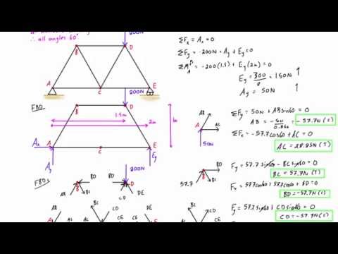 Use setFixedTransform to specify the body-to-body transformation using DH parameters. Fixed transform from joint to parent frame, Fixed transform from child body to joint frame.
  (University of Colorado Boulder, Department of Chemical and Biological Engineering) Based on your location, we recommend that you select: . -you will use trigonometry to break the reactionary force at A into horizontal and vertical components.
  offers. The method of joint involves successively isolating each joint in a truss system and determining the axial forces in the members meeting at the joint by applying the equations of equilibrium. In this tutorial, we will explain how to use the method of joints to calculate the internal member forces in a truss system or structure. It is important to remember that all the forces must sum to zero for both the x and y-direction. If this initial assumption is incorrect, the computed values of the axial forces will be negative, signifying compression.
  Based on your location, we recommend that you select: . The LibreTexts libraries arePowered by NICE CXone Expertand are supported by the Department of Education Open Textbook Pilot Project, the UC Davis Office of the Provost, the UC Davis Library, the California State University Affordable Learning Solutions Program, and Merlot. If you assumed that all forces were tensile earlier, remember that negative answers indicate compressive forces in the members. Besides, only axial loads are assumed, so that torsion, bending and shear stresses are neglected and cannot be determined by this method. Other MathWorks country Procedure for Analysis. Method of section: This method entails passing an imaginary section through the truss to divide it into two sections. Your guide to SkyCiv software - tutorials, how-to guides and technical articles. \end{array}\). Use this list as one of the inputs to the custom function randomOpPoint that creates an operating point specifying random velocities for all the joints. +\rightarrow \sum F_{x}=0 \\ slides along a given axis. Remember to specify if each member is in tension or compression. Now that the forces on the joint have been broken into horizontal and vertical components the two summation equations can be written as shown. WebThis means that to solve completely for the forces acting on a joint, we must select a joint with no more than two unknown forces involved. WebCreate a Mechanism with Different Joints in MATLAB This example shows how to model a mechanism that contains different types of joints in MATLAB. -80(6)+80(3)-F_{C D}(3)=0 \\
  It also shows a way of setting operating point targets for the joint primitives of the joints. type predefines certain properties when creating the joint.
  Since the Theory of Deformations is not considered in this program, displacements of the structures are not computed. You can now solve for the forces at joint B. First, we calculate the reactions at the supports. % Row 3: 3-DOF and 4-DOF multi-primitive joints, Create a Mechanism with Different Joints in MATLAB. All the members of the structure satisfy the simplification hypothesis of the method of joints. As an example of a free body diagram of an entire simple truss, consider this truss with joints A,B,C,D. A free-body diagram is a diagram that clearly indicates all forces acting on a body, in this case the body being the truss. We also acknowledge previous National Science Foundation support under grant numbers 1246120, 1525057, and 1413739. Procedure for Analysis. WebThe method of joints analyzes the force in each member of a truss by breaking the truss down and calculating the forces at each individual joint. WebPart 1. freedom (DOF) joint that rotates around a given axis. Loads on Truss Nodes . First, calculate the reaction forces by doing a moment balance around joint and force balances in the and directions: where and are the reaction forces at joint in the and directions, is the reaction force at joint , is the width of the members and is the point load force at joint . In this program, the basic elimination approach is used to reduce the global matrix and find the displacements at the nodes. SkyCiv Truss can calculate the method of joints automatically for you. an attachment point. Now we consider the forces in the x-direction. This example shows how to model a mechanism that contains different types of joints in MATLAB. Again, if we look at summing the forces in the x-direction, we can see there is only one member that has any force in the x-direction. Create a Multibody object and add the necessary components, such as WorldFrame and Gravity. Recall that in this method, a free-body diagram of each joint is sketched and the forces acting on the joint are summed in the x- $\Sigma F_x = 0$ and $\Sigma F_y = 0$, MATHalino - Engineering Mathematics Copyright 2023, Problem 404 Roof Truss - Method of Joints, Problem 406 Cantilever Truss - Method of Joints, Problem 407 Cantilever Truss - Method of Joints, Problem 408 Warren Truss - Method of Joints, Problem 409 Howe Roof Truss - Method of Joints, Problem 410 Pratt Roof Truss - Method of Joints, Problem 411 Cantilever Truss by Method of Joints, Problem 412 Right Triangular Truss by Method of Joints, Method of Joints | Analysis of Simple Trusses, Method of Sections | Analysis of Simple Trusses, Method of Members | Frames Containing Three-Force Members. 5.1 Classify the trusses shown in Figure P5.1a through Figure P5.1r. The last element of the DH parameters, theta, is ignored because the angle is dependent on the joint position. revolute 0 The method centers on the joints or connection points between the members, and it is usually the fastest and easiest way to solve for all the unknown forces in a truss structure. MathWorks is the leading developer of mathematical computing software for engineers and scientists. You have now learned how to analyze a simple truss by the method of joints. Bodies remain fixed To determine the number of unknown reactions in excess of the equation of equilibrium for the indeterminate trusses, additional equations must be formulated based on the compatibility of parts of the system. This will help you keep everything organized and consistent in later analysis. Accordingly, we know member 2 must be generating a force that is pulling the point to the right to maintain the forces in the x-direction. F_{D C}=F_{D A}=-7.34 \mathrm{kN} Procedure for Analysis. We also acknowledge previous National Science Foundation support under grant numbers 1246120, 1525057, and 1413739. Truss Tutorial 1: Analysis and Calculation using Method of Joints Step 1: Calculate the Reactions at the Supports. If this initial assumption is wrong, the calculated member forces will be negative, showing that they are in compression. You must create a new Joint object and use replaceJoint to ensure the downstream body geometry is unaffected. All assumptions of Rational Mechanics are made in order to mantain the structure as a rigid body. Your calculations will give you a negative or a positive number designating the real direction of the force. The order of the calculations shown is the order that the joints are solved in. You can also calculate the side length of a triangle if two of the side are known by using Pythagorea's Theorem which says the square of the hypotenuse is equal to the sum of the square of the adjacent side plus the square of the opposite (a^2+b^2=c^2). This page titled 5.6: Methods of Truss Analysis is shared under a CC BY-NC-SA 4.0 license and was authored, remixed, and/or curated by Ren Alderliesten (TU Delft Open) via source content that was edited to the style and standards of the LibreTexts platform; a detailed edit history is available upon request. If the rigid body that contains this joint is added to a robot model, the joint type predefines certain properties when creating the joint. If this initial assumption is wrong, the determined member axial force will be negative in the analysis, meaning that the member is in compression and not in tension. equilateral. PositionLimits. type. In our example, the horizontal distance is 3m while the vertical is 5m leaving us with the hypotenuse equal to approximately 5.83 m. Using this, we can deduce that the normal force component of member 1 is equal to (5.83)/(5) times the vertical force of 2.5 kN. A close examination will show that the joint that meets this requirement is joint \(G\). WebCreate a Mechanism with Different Joints in MATLAB This example shows how to model a mechanism that contains different types of joints in MATLAB. (default). This page titled 5.4: Method of Joints is shared under a CC BY-SA 4.0 license and was authored, remixed, and/or curated by Jacob Moore & Contributors (Mechanics Map) via source content that was edited to the style and standards of the LibreTexts platform; a detailed edit history is available upon request. In this program, the basic elimination approach is used to reduce the global matrix and find the displacements at the nodes. Using the method of joint, determine the axial force in each member of the truss shown in Figure 5.10a. In this situation, any force pushing up will have no possible resisting action, as there is no other member that is able to provide a downward force to keep the point static.
  Trusses can be externally or internally determinate or indeterminate. The Golden Gate Bridge has a unique truss incorporated into its design. The analysis for isosceles triangles will be similar. To calculate forces on a truss you will need to use trigonometry of a right triangle. Then, under the drop-down menu, select "calculate moment" to see the moment balance around joint and calculate the reaction force at joint . Published:September82017. MATLAB program for 2D truss analysis (FEM). This method involves passing an imaginary section through the truss so that it divides the system into two parts and cuts through members whose axial forces are desired. By default, the rigidBody object comes with a fixed joint.